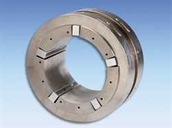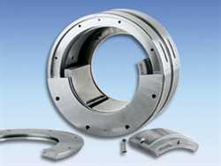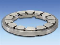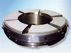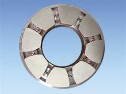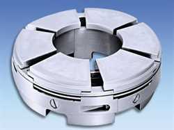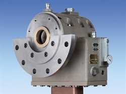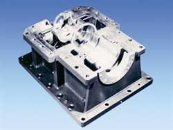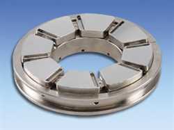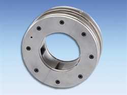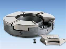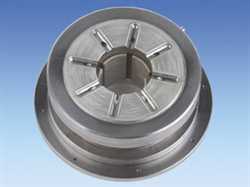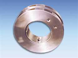
Kingsbury Fixed Profile Journal Bearing
Kingsbury
Product Code: Fixed Profile Journal
Brand: Kingsbury
GET OFFER: info@imtek.com.tr
Description for Kingsbury Fixed Profile Journal Bearing
Kingsbury now offers a standard line of plain journal bearings in addition to our proven tilting pad design. KN thick-walled metric bearings are designed for rotating machinery such as turbines, pumps and gearboxes, operating at sliding speeds between 5 m/s to 90 m/s and shaft diameters ranging between 25 and 700 mm. Standard designs can be customized for individual applications to suit any shaft size. For shaft sizes above 700 mm, bearings are custom made to your specifications. Kingsbury will also manufacture bearings to customer supplied drawings and specifications. Benefits & Features Our standard sizes and designs make the selection process easy and efficient. All standard parts are babbitt-lined, steel-backed and manufactured to demanding tolerances. Our standard babbitt material is ASTM B23 Grade 2, but many other grades and types are available. A thrust capacity of up to 1.7 MPa can be provided on KN thick wall bearings or by separate thrust washers. For higher loads and faster sliding speeds, tilting pad bearings should be considered. For the most part, these plain journal bearings are perfect for lower speed, moderate load applications and provide a reliable alternative to more expensive bearing styles. See Table 1 in PDF for selection information. Polymer linings are available to extend performance limits, to operate with non-oil lubricants such as water, or to be used in harsh environments. Lubrication Requirements These bearings require a continuous supply of high quality lubricating oil. For most applications, we recommend ISO VG 32, 46 or 68 (without EP additives) supplied at 45°C to 55°C and filtered to 25 ?m or better. The oil both lubricates and removes the heat that is generated within the oil film. The oil flow rate for plain bearings is a function of speed, load, clearance, and viscosity. The inlet pressure to the bearing has little effect on the flow rate and only needs to be 0.25 bar (but can be higher). To increase the flow rate and lower bearing temperatures, the bore profile should be modified (see Table 1 in PDF). Kingsbury's state-of-the-art computer calculation models can accurately predict performance for any of the different profiles listed in the table. Clearances The clearance between the bearing and the shaft is a critical parameter for successful performance and operation. The clearance must be large enough to allow for thermal expansion and provide space for the hydrodynamic oil film. In general, tighter clearance promotes rotor stability, while looser clearance provides for lower oil film temperatures. Often the bearing designer must balance these competing parameters. Figure 1 shows Kingsbury's recommended minimum clearance. The maximum clearance is found by adding the bearing bore tolerance (usually H7) to the shaft tolerance (H6.) The shaft size can be found by subtracting the minimum clearance value from the nominal bearing size. Example: 150 mm bearing operating at 75 m/sec Min clearance = 1.6 ?m x 150 = 0.24mm (Reference Figure 1) Shaft = 150 - 0.24 = 149.76 H6 Bearing = 150 H7 Diameter & Length Shaft diameter is usually fixed by the machine's torque or stability considerations. For the shaft, we recommend an H6 tolerance with a surface finish of Ra 0.4 ?m. Load capacity varies with bearing lengths; there are 3 standard ratios of length to diameter. Other ratios can also be supplied to optimize performance. As an initial guide, radial load divided by projected area should not exceed 3.8 MPa. Note: Projected area can be found by multiplying the bearing's length by the diameter. Installation And Tolerances Proper installation is critical to optimal performance. We recommend bearing housing bores to be machined to an H7 tolerance. To insure proper installation, bearings are supplied with zero or a slight positive free spread. Free spread varies with shaft diameter and wall thickness. KN bearings are supplied with an anti-rotation and alignment dowel pin for proper location within the bearing housing. The pin should be located in a milled slot at the joint line for ease of assembly. The bearing must be located so that the load angle is 90° ± 30° to the bearing split line in most cases. Three lobe and four lobe bearings should be closely reviewed for proper orientation relative to the load vector. Bearing Temperature And Measurement Bearing problems and failures are in most cases reflected by elevated oil film temperatures. Normal operation creates heat from the work being done by the supporting oil film. This temperature can be predicted by Kingsbury's state of the art computer calculation models. By measuring the bearing surface temperature, very close to the oil film, it is possible to determine if the bearing is operating properly. If the normal temperatures are exceeded, the machine should be stopped before failure occurs. Kingsbury recommends that the temperature sensor be installed along the load angle or 10°-20° downstream of the load angle, toward the trailing edge. The maximum design running temperature should be 115°C or less. The alarm should be set 8°C above normal or expected values and the trip 7°C above the alarm. In no case should the maximum trip temperature be above 130°C. Bore Profiles And Dynamic Characteristics Special bore profiles are available for rotor stability in high speed, low load situations and to reduce bearing temperatures. Table 1 provides a detailed comparison of the advantages and disadvantages for different types of bore profiles that are available. In most cases, a decision must be made between cost and performance. Information about how the bearing characteristics affect the system stability is important with regard to this decision. Kingsbury can provide stiffness and damping values for any of these bearing types based on your application. Figure 1: Clearance Vs. SpeedRecommended Products For Kingsbury
